- Introduction
- Overview of the Double Pulse Test
- Why Use a Double Pulse Test?
- Equipment Required for Double Pulse Testing
- Step-by-Step: How to Perform a Double Pulse Test
- 1. Setup
- 2. First Pulse
- 3. Recovery Period
- 4. Second Pulse
- 5. Data Analysis
- Common Challenges and Tips
- Parasitic Inductance
- Safety Considerations
- Temperature Effects
- Example of DPT Results Table
- Conclusion
- Whenever You’re Ready, Here Are 5 Ways We Can Help You
How do engineers accurately measure the switching performance of power semiconductors like MOSFETs and IGBTs?
Enter the double pulse test—a standard method used to evaluate dynamic switching parameters, such as energy losses and reverse recovery characteristics.
This test plays a critical role in designing and optimizing power electronics, especially for high-performance applications involving silicon carbide (SiC) or gallium nitride (GaN) devices.
| Key Takeaway |
|---|
| The double pulse test provides a precise way to evaluate the switching performance of power semiconductors by measuring critical parameters like energy losses, voltage spikes, and reverse recovery times. It plays a key role in optimizing circuit designs for efficiency and reliability, especially in high-performance applications involving MOSFETs, IGBTs, and wide bandgap devices. |
Overview of the Double Pulse Test
The double pulse test (DPT) evaluates how a power semiconductor behaves during two crucial switching events: turn-on and turn-off.
Engineers use it to assess the energy losses that occur in these transitions, as well as the reverse recovery behavior of the freewheeling diode in the circuit.
A typical DPT setup consists of:
- Power switch (e.g., MOSFET or IGBT)
- Diode (for reverse recovery evaluation)
- DC-link capacitor (energy storage)
- Load inductor (to control current flow)
- Oscilloscope (to capture switching waveforms)
The method involves generating two consecutive pulses.
The first pulse magnetizes the load inductor to a target current level. After a brief off period, the second pulse measures how the device behaves under nominal current flow, capturing critical switching parameters like switching losses, peak voltages, and recovery times.
Why Use a Double Pulse Test?
DPT offers several advantages:
- Accurate switching analysis – You capture real-time switching waveforms during turn-on and turn-off transitions.
- Loss evaluation – The test helps identify switching and conduction losses, essential for optimizing power circuits.
- Characterization across operating points – Engineers can use DPT across different voltages and temperatures, ensuring the device meets performance targets under all conditions.
Equipment Required for Double Pulse Testing
To run a successful double pulse test, you need:
- Function Generator – Supplies the gate drive signals. Some advanced models include pre-configured DPT applications for ease of use.
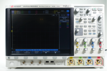
- Oscilloscope – Measures voltage and current waveforms. Models with high bandwidth are preferred, especially for wide bandgap semiconductors like SiC and GaN, which switch at higher frequencies.
- Current Probes and Voltage Probes – Differential probes are essential to accurately capture switching waveforms while minimizing noise and ground loops.
- DC Power Supply – Provides power to the device under test (DUT).
- Load Inductor – Controls the rate of current change (dI/dt) to prevent damage during testing.
Advanced oscilloscopes offer automated measurements, streamlining data collection and analysis.
Step-by-Step: How to Perform a Double Pulse Test
Performing a double pulse test (DPT) accurately ensures you capture reliable data to evaluate the switching behavior of semiconductors.
Below is a detailed breakdown of the process.
1. Setup
Connect the device under test (DUT), power supply, load inductor, and probes. Ensure that all probes—especially differential voltage probes and current sensors—are properly rated for the operating voltage. Take the following measures for effective setup:
- Ground everything correctly to avoid noise and signal interference.
- Shorten cables and minimize loops to reduce parasitic inductance.
- Place the DUT in an enclosure to ensure safety during testing, particularly at high voltages.
2. First Pulse
Apply the first pulse to the gate of the DUT to magnetize the load inductor. This builds up the desired current, and when the switch turns off, you can capture key metrics:
- Voltage overshoot: Monitor the peak voltage when the current is interrupted, which helps evaluate the robustness of the switch.
- Turn-off energy loss: Use the oscilloscope to measure the energy lost during this transition.
This step ensures the device can handle fast current changes without excessive voltage spikes that could damage components.
3. Recovery Period
Allow time for the device to fully de-energize before applying the second pulse. During this phase:
- The diode must recover, discharging any residual energy.
- Waiting ensures that transient effects from the first pulse do not interfere with the second pulse measurements.
This step is critical to prevent incorrect readings or potential device failure due to incomplete recovery.
4. Second Pulse
Apply the second pulse to test the DUT’s turn-on behavior under nominal current conditions. The current flows back through the inductor and diode, and the oscilloscope captures important parameters:
- Turn-on energy loss: Identify how much energy dissipates when the switch turns on.
- Reverse recovery characteristics: Measure the recovery time of the freewheeling diode to ensure minimal switching losses and proper circuit operation.
This pulse helps determine the switching efficiency and identifies areas where design improvements are necessary.
5. Data Analysis
Analyze the collected data using oscilloscope software. Focus on key metrics such as:
- Turn-on and turn-off losses: These values are essential for optimizing energy efficiency and managing heat dissipation.
- Voltage spikes and overshoot: Ensure peak voltages remain within safe operating limits to avoid component damage.
- Switching frequency optimization: Balance switching speed with energy efficiency to avoid excess heat buildup.
By following these steps, you can evaluate the DUT’s performance under real-world conditions and make adjustments to improve the reliability of your power electronics design.
High-performance oscilloscopes with DPT software features can automate much of this process, simplifying complex measurements and ensuring precise data analysis.
Common Challenges and Tips
Even with the right setup, double pulse testing comes with a set of challenges that can affect measurement accuracy and safety.
Understanding these challenges allows you to implement practical solutions for more reliable results.
Parasitic Inductance
Cables, PCB traces, and component connections can introduce parasitic inductance, affecting the accuracy of double pulse test (DPT) measurements.
This additional inductance creates voltage spikes during switching, distorting the captured waveforms. To minimize these effects:
- Use shorter cables and tightly controlled PCB layouts.
- Place components as close together as possible to reduce the inductive loop area.
- Add decoupling capacitors to stabilize circuits where necessary.
- Use differential probes and Rogowski coils to reduce the impact of noise on measurements.
Safety Considerations
Handling high-voltage circuits in a DPT setup requires strict safety measures to avoid accidents. The test involves fast-switching events that can generate dangerous voltage spikes.
Keep the following safety protocols in mind:
- Use proper enclosures to prevent accidental contact with live components.
- Ensure that your equipment, including probes, has appropriate voltage ratings to handle the operating range.
- Install an emergency power-off switch within easy reach.
- Follow the buddy system during high-voltage tests, ensuring another person is present for emergencies.
Temperature Effects
Temperature plays a significant role in semiconductor performance.
As temperature increases, switching losses, reverse recovery behavior, and overall efficiency can change dramatically.
Testing your device across the full expected operating temperature range ensures it performs reliably under all conditions.
Here are practical tips for managing temperature during DPT:
- Monitor junction temperature: Use thermal sensors to track the device's junction temperature. Many semiconductors show degraded switching performance at higher temperatures.
- Evaluate cooling solutions: Measure energy losses under different thermal conditions to size cooling components correctly (e.g., heatsinks or fans).
- Simulate worst-case scenarios: Test at maximum operating temperatures to uncover potential failure points.
- Use temperature-controlled environments: If possible, perform DPT inside chambers that allow you to replicate extreme operating temperatures.
Managing parasitic inductance, ensuring proper safety, and accounting for temperature variations are critical steps for reliable and accurate DPT results.
Example of DPT Results Table
| Parameter | Description | Why It Matters | Typical Values | Measured Using |
| Turn-on Energy Loss (Eon) | Energy dissipated when the switch turns on | Helps optimize switching efficiency | 0.5 – 2.0 mJ | Oscilloscope with current and voltage probes |
| Turn-off Energy Loss (Eoff) | Energy dissipated when the switch turns off | Impacts thermal management and reliability | 0.4 – 1.5 mJ | Oscilloscope + Current Probe |
| Peak Turn-off Voltage | Maximum voltage spike during turn-off | Prevents semiconductor failure | 250 – 600 V | Voltage Probe |
| Reverse Recovery Time (trr) | Time taken for the diode to recover after conducting | Reduces switching losses and EMI | 30 – 100 ns | Oscilloscope with fast sampling rates |
| Overshoot Voltage | Voltage exceeding the supply voltage during switching | Ensures design stays within safe limits | 10 – 30% above supply | High-bandwidth Voltage Probe |
| Switching Frequency | Frequency at which the device operates | Affects overall power efficiency | 20 kHz – 1 MHz | Function Generator + Oscilloscope |
| Junction Temperature | Temperature at the semiconductor junction | Impacts device lifespan and performance | 25°C – 150°C | Thermal Sensor/Temperature Management |
Conclusion
The double pulse test is essential for evaluating the dynamic performance of power semiconductors, providing insights into switching losses, voltage overshoot, and reverse recovery behavior.
Mastering this method ensures that your designs meet performance and reliability standards under real-world operating conditions. Using high-quality equipment like oscilloscopes, current probes, and function generators makes a significant difference in accuracy and efficiency.
For engineers looking to upgrade their testing setup, consider Keysight's Used Equipment Store, which offers premium oscilloscopes, spectrum analyzers, function generators, and multimeters.
Our pre-owned products deliver high performance at a fraction of the cost, helping you maintain quality while staying within budget.

Whenever You’re Ready, Here Are 5 Ways We Can Help You
- Browse our Premium Used Oscilloscopes.
- Call tech support US: +1 800 829-4444
Press #, then 2. Hours: 7 am – 5 pm MT, Mon– Fri - Talk to our sales support team by clicking the icon (bottom right corner) on every offer page
- Create an account to get price alerts and access to exclusive waitlists.
- Talk to your account manager about your specific needs.
