- Introduction
- Understanding the Leading Edge
- Importance in Signal Analysis
- Key Characteristics of the Leading Edge
- Rise Time
- Overshoot and Ringing
- Practical Tips for Analyzing the Leading Edge
- 1. Set Proper Trigger Levels
- 2. Use Appropriate Bandwidth
- 3. Check for Signal Integrity Issues
- 4. Adjust Sampling Rate
- 5. Analyze Waveform Stability
- Applications in Different Fields
- Telecommunications
- Radar Systems
- Consumer Electronics
- Medical Imaging
- Automotive Systems
- Summary Table of Leading Edge Characteristics
- Conclusion
- Whenever You’re Ready, Here Are 5 Ways We Can Help You
このページの日本語版は、現在ご利用いただけません。現在コンテンツの追加および翻訳作業を行なっており、近日公開予定です。
ご投票ありがとうございますImagine you're watching a sprinter poised at the starting line—the tension builds, the starter pistol fires, and in a burst of energy, the runner lunges forward.
In electronics, a similar explosive moment occurs at the leading edge of a signal. This critical juncture, where the signal first leaps from its lowest to its highest point, sets the pace for everything that follows.
Whether you're an electrical engineer fine-tuning a sophisticated circuit or a hobbyist dabbling in digital electronics, understanding the leading edge can change how you approach signal analysis and testing.
Understanding the Leading Edge
The leading edge refers to the front part of a signal waveform where the signal begins to rise from its lowest value (baseline) to its highest value (peak). This transition triggers timing circuits and is used to measure the speed and timing of a signal.
Importance in Signal Analysis
- Timing measurement: The leading edge is used to determine the timing characteristics of a signal, which are essential for synchronizing and timing operations in electronic circuits.
- Triggering events: In oscilloscopes, the leading edge often serves as a trigger point for capturing data. This helps in isolating specific events within a complex signal.
| Key Takeaway |
|---|
| The leading edge of a signal determines the timing, synchronization, and overall integrity of electronic communications and systems. Understanding its characteristics, such as rise time and overshoot, is important for improving performance and troubleshooting potential issues in any electronic circuit. |
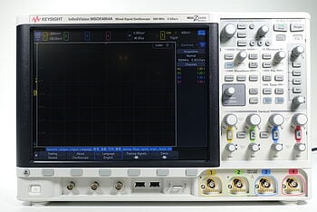
Discover Our Selection of Used Oscilloscopes
Key Characteristics of the Leading Edge
The leading edge of a signal is not just the starting point of a waveform; it is a critical feature that informs the overall behavior of electronic circuits. Understanding its characteristics, such as rise time, overshoot, and ringing, provides valuable insights into signal integrity and performance.
Rise Time
Rise time is a characteristic of the leading edge, reflecting how quickly a signal transitions from a low state to a high state.
It is quantitatively defined as the duration it takes for a signal's amplitude to climb from a predefined lower percentage (typically 10% of the peak value) to a higher percentage (usually 90% of the peak value).
This metric is important because it affects how a signal can be used for timing and triggering purposes, impacting everything from digital communication to automated response systems.
Overshoot and Ringing
Overshoot occurs when the signal exceeds its target amplitude in the initial transition of the leading edge, often followed by ringing—oscillations that gradually settle down to the steady-state value.
These phenomena are particularly telling, as they can reveal potential issues in the circuit, such as excessive noise, inadequate damping, or instability.
Knowing how to deal with overshoot and ringing will help you to maintain the integrity of signal processing and ensure that the electronic system is reliable.
Practical Tips for Analyzing the Leading Edge
Precise and accurate setup is key to obtaining meaningful results with an oscilloscope or similar testing equipment. Here are some tips to guide you:
1. Set Proper Trigger Levels
To obtain consistent and reliable capture of the leading edge, you need to set the correct trigger level on your oscilloscope. The trigger level determines at what point the oscilloscope starts to record the signal. It should be set just above the baseline noise level but below the lowest expected amplitude of the leading edge. This prevents false triggers and ensures that the oscilloscope captures the complete rising edge of the signal every time.
2. Use Appropriate Bandwidth
An oscilloscope with the right bandwidth will accurately capture high-frequency signals without loss of detail. The bandwidth of the oscilloscope must be higher than the highest frequency component of the signal you are measuring.
A rule of thumb is to use an oscilloscope with a bandwidth at least five times higher than the highest frequency of the signal. This avoids attenuation of the signal’s higher frequency components, ensuring a true representation of the signal’s shape.
3. Check for Signal Integrity Issues
Regular checks for signal integrity issues like overshoot and ringing will help you diagnose and correct problems in circuit design. Overshoot and ringing can result from a variety of factors, including impedance mismatches, insufficient damping, or feedback issues.
Observing these effects can alert you to potential design flaws that may affect the performance of the circuit. Use the oscilloscope’s measurement functions to quantify the amount of overshoot and the frequency and damping of ringing oscillations
4. Adjust Sampling Rate
Make sure the sampling rate of your oscilloscope is adequate to capture the details of the leading edge. A higher sampling rate provides a more accurate and detailed view of the signal’s transition, capturing transient details that a lower rate might miss.
The minimum sampling rate should be twice the oscilloscope's bandwidth to fully leverage its capabilities and comply with the Nyquist rate, which prevents aliasing and ensures a faithful representation of the signal.
5. Analyze Waveform Stability
Monitoring the stability and repeatability of the leading edge in repetitive or varying conditions can provide insights into the robustness and reliability of a circuit.
Use features like waveform averaging, which can reduce noise and reveal underlying trends or anomalies in the signal. This is particularly useful in noisy environments or when dealing with low-amplitude signals.
Implementing these tips will improve your ability to accurately analyze the leading edge, leading to better understanding and optimization of electronic systems.
Applications in Different Fields
The leading edge of a signal is instrumental across a wide array of technical fields, influencing both the design and function of various systems. Understanding its applications can improve precision and efficiency in many aspects of technology.
Telecommunications
In telecommunications, the leading edge is crucial for assessing the performance and integrity of data transmission. It helps in timing synchronization between transmitting and receiving devices, which is vital for error-free communication.
For instance, in digital communications, the exact point where the signal rises significantly influences how bits are timed and interpreted, directly affecting the accuracy and speed of data transfer.
Radar Systems
For radar systems, the leading edge is fundamental in determining the range and position of objects. Radars emit pulses and measure the time interval between the transmission and reception of these pulses.
The leading edge of the received pulse marks the start of this interval, enabling precise calculations of distances. This capability is critical in applications ranging from aviation safety and weather forecasting to military and space exploration.
Consumer Electronics
In consumer electronics, the leading edge is key to ensuring devices such as smartphones, tablets, and televisions respond correctly to input signals. It affects how quickly a device can process and react to user commands, impacting user experience and device functionality.
For instance, in touch screen technology, the speed and accuracy with which a device detects changes in signal from touch inputs can enhance the responsiveness and sensitivity of the interface.
Medical Imaging
The leading edge also plays a significant role in medical imaging technologies, such as ultrasound and MRI. In these applications, the precise measurement of the leading edge of a signal can help in creating accurate and detailed images of internal body structures. This precision is crucial for diagnosing conditions and planning treatments with high degrees of confidence.
Automotive Systems
In automotive technology, particularly in safety systems like airbag controllers and anti-lock braking systems (ABS), the leading edge of a signal from sensors (such as accelerometers and speed sensors) triggers the deployment of safety mechanisms.
The ability to accurately detect and process these signals can be the difference between effective and failed deployment, significantly impacting vehicle safety and passenger protection.
By leveraging the characteristics of the leading edge, professionals in these fields can improve the performance, reliability, and safety of their technologies, making it a cornerstone of modern electronic design and application.
Summary Table of Leading Edge Characteristics
| Characteristic | Description | Importance |
|---|---|---|
| Rise Time | Time it takes to rise from 10% to 90% amplitude | Crucial for timing measurements |
| Overshoot | Extent to which signal exceeds its peak value | Indicates potential instability |
| Ringing | Oscillations following the overshoot | Reflects noise and damping in the system |
| Settling Time | Time taken for the signal to stabilize within a specific error band after a transition | Important for ensuring stable operation after changes |
| Propagation Delay | Time delay between the application of a signal at the input and the corresponding output response | Critical in digital circuits for synchronization |
| Amplitude Accuracy | The accuracy with which a system can measure and reproduce the amplitude of the leading edge | Essential for precise signal processing and control |
Explore Keysight’s Range of Oscilloscopes Today
Select up to 3 instruments to compare
Select another instrument to compare
![]()
Starting at
Select another instrument to compare
![]()
Starting at
Select another instrument to compare
![]()
Starting at
Conclusion
Understanding the leading edge of a signal helps to optimize the performance of electronic systems across various fields.
Key characteristics like rise time, overshoot, and ringing provide insights into signal integrity and influence the precision and reliability of technological applications. Whether you're designing new devices or troubleshooting existing systems, mastering the analysis of the leading edge can significantly enhance your capabilities.
Visit Keysight Used Equipment Store to find premium used oscilloscopes, spectrum analyzers, function generators, and multimeters that deliver professional-grade reliability at a fraction of the cost. Explore our selection and empower your electronics projects with top-quality instrumentation.
Whenever You’re Ready, Here Are 5 Ways We Can Help You
- Browse our Premium Used Oscilloscopes.
- Call tech support US: +1 800 829-4444
Press #, then 2. Hours: 7 am – 5 pm MT, Mon– Fri - Talk to our sales support team by clicking the icon (bottom right corner) on every offer page
- Create an account to get price alerts and access to exclusive waitlists.
- Talk to your account manager about your specific needs.
