- Introduction
- Understanding Resonant Frequency
- Resonant Frequency in RLC Circuits
- Practical Applications of Resonant Frequency
- 1. Filters and Signal Processing
- 2. Oscillators and Signal Generation
- 3. Tuning Circuits for Communication Systems
- 4. Wireless Power Transfer and Inductive Charging
- 5. Mechanical and Structural Applications
- Measuring Resonant Frequency: Best Tools and Techniques
- Best Tools for Measuring Resonant Frequency
- Tips for Accurate Measurement
- Choosing the Right Tool
- Quality Factor (Q Factor) and Its Importance
- Conclusion
- Whenever You’re Ready, Here Are 5 Ways We Can Help You
Every system has a natural frequency at which it oscillates with maximum amplitude. In circuits, this phenomenon affects filters, oscillators, antennas, and wireless power transfer, making resonance a key factor in performance and efficiency.
Understanding and accurately measuring resonant frequency helps engineers design precise and optimized electronic systems.
Understanding Resonant Frequency
Resonant frequency is the natural frequency at which a system oscillates with the greatest amplitude.
When an external force matches this frequency, the system's response becomes maximal. In electrical circuits, especially those involving inductors and capacitors, this concept is fundamental.
Resonant Frequency in RLC Circuits
In circuits containing resistors (R), inductors (L), and capacitors (C), resonance plays a pivotal role. The resonant frequency (fr) for a series or parallel RLC circuit is determined by the formula:
\(\mathit{f_r = {1 \over 2\pi\sqrt{LC}}}\)
Where:
- L = Inductance in henries (H)
- C = Capacitance in farads (F)
At this frequency:
- Series RLC Circuit: The impedance is minimized, allowing maximum current flow.
- Parallel RLC Circuit: The impedance is maximized, minimizing the current through the source.
| Key Takeaway |
|---|
| Resonant frequency is the natural frequency at which a system oscillates with maximum amplitude, making it crucial for designing efficient circuits in filters, oscillators, and communication systems. |
Practical Applications of Resonant Frequency
Resonant frequency plays a crucial role in many electrical and electronic systems. Engineers leverage resonance to design efficient circuits that improve signal processing, communication, and power management. Here are some key applications:
1. Filters and Signal Processing
Resonant circuits act as frequency-selective filters, allowing engineers to isolate or block certain frequencies. These filters are critical in:
- Low-pass filters: Allow frequencies below a certain threshold while attenuating higher ones.
- High-pass filters: Permit high frequencies and block lower ones.
- Band-pass filters: Pass a specific range of frequencies and reject those outside the range.
- Band-stop (notch) filters: Suppress a particular frequency band while passing others.
Filters based on resonance are widely used in audio processing, radio communications, and medical imaging devices like MRI scanners.
2. Oscillators and Signal Generation
Resonant circuits are fundamental in generating stable and precise signals. Oscillators use resonance to maintain a consistent frequency output, making them essential for:
- Clock generation in microprocessors: Quartz crystal oscillators provide accurate timing signals for digital circuits.
- RF and microwave communication: Radio transmitters and receivers rely on oscillators to modulate and demodulate signals.
- Test and measurement equipment: Function generators and waveform synthesizers use oscillators for frequency generation.
3. Tuning Circuits for Communication Systems
Resonant circuits help select specific frequencies from a broad range of signals, enabling radio, television, and wireless communication.
- AM/FM radios use LC tuning circuits to filter out unwanted stations and amplify the desired signal.
- TV tuners use resonance to select the right channel frequency.
- Antenna matching networks rely on resonance to ensure maximum power transfer between antennas and transmitters.
4. Wireless Power Transfer and Inductive Charging
Resonance is a key principle behind wireless power transfer technologies used in:
- Smartphone wireless charging: Wireless chargers operate at resonant frequencies that efficiently transfer energy.
- Electric vehicle (EV) charging: Resonant inductive coupling enables wireless power transfer for charging electric cars.
- Medical implants: Devices like pacemakers use wireless power through resonance to eliminate the need for battery replacements.
5. Mechanical and Structural Applications
Resonance is not limited to electrical circuits. Engineers also apply it in:
- Vibration analysis: Identifying structural weaknesses in buildings, bridges, and aircraft.
- Resonance testing in mechanical components: Ensuring that components do not experience destructive resonance in engines and turbines.
Understanding resonant frequency allows engineers to optimize circuit performance, improve efficiency, and prevent system failures.
Whether designing communication systems, power transfer solutions, or test equipment, resonance is a fundamental concept that enhances electrical and mechanical engineering applications.
Measuring Resonant Frequency: Best Tools and Techniques
Accurate measurement of resonant frequency is essential for designing and optimizing electrical circuits. Different tools are used depending on the circuit type, required precision, and frequency range.
Best Tools for Measuring Resonant Frequency
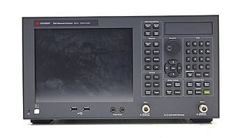
1. Vector Network Analyzer (VNA)
- Best for RF and microwave circuits.
- Measures scattering parameters (S-parameters) to determine the resonant frequency and quality factor (Q).
- Provides a highly accurate frequency response over a wide range, making it ideal for antenna design, filters, and RF components.
- Used extensively in wireless communication, radar, and high-frequency circuit analysis.
2. LCR Meter (Impedance Analyzer)
- Best for low to mid-frequency circuits (e.g., audio filters, power electronics).
- Measures inductance (L), capacitance (C), and resistance (R) at different frequencies to detect resonance conditions.
- Provides a direct measurement of impedance and phase angle, eliminating the need for signal generators or external probes.
- Ideal for testing components, checking resonators, and tuning RLC circuits.
3. Spectrum Analyzer
- Best for measuring resonance in signal processing applications.
- Spectrum Analyzers detect frequency peaks and bandwidth by analyzing how a circuit responds to a range of input signals.
- Often paired with a tracking generator to provide real-time frequency domain analysis.
4. Oscilloscope with Function Generator
- Best for general-purpose circuit testing and troubleshooting.
- Oscilloscopes allow engineers to apply a variable-frequency signal and observe voltage amplitude changes.
- Helps identify the frequency at which voltage peaks, corresponding to resonance.
- Works well in low-frequency and audio applications, but may have limitations in RF testing due to bandwidth constraints.
Tips for Accurate Measurement
- Calibration: Ensure measurement tools (VNAs, oscilloscopes, LCR meters) are properly calibrated.
- Bandwidth considerations: Use an oscilloscope with sufficient bandwidth or a VNA with the correct frequency range.
- Minimize parasitics: Reduce unwanted inductance and capacitance in test leads and circuit layout.
- Use proper probes: For high-frequency circuits, use active probes to avoid loading effects.
Choosing the Right Tool
Measurement Tool | Best For | Pros | Cons |
Vector Network Analyzer (VNA) | RF and microwave resonance analysis | Highly accurate, measures S-parameters | Expensive, requires expertise |
LCR Meter (Impedance Analyzer) | Low- to mid-frequency component testing | Direct inductance/capacitance measurement | Limited to low-frequency applications |
Spectrum Analyzer | Signal processing and communication circuits | Provides a frequency domain view | May need a tracking generator |
Oscilloscope + Function Generator | General-purpose resonance testing | Easy to use, visualizes waveforms | Less precise for high-frequency circuits |
By choosing the right tool, you can efficiently measure resonant frequency and optimize circuit performance.
Quality Factor (Q Factor) and Its Importance
The Q Factor quantifies how sharp and selective a resonant circuit is. It measures the efficiency of energy storage versus energy dissipation in a system. A higher Q Factor means lower energy loss per cycle, resulting in a more selective and stable resonance.
Formula
The Q Factor is defined as:
Q = fr / BW
Where:
- Q = Quality Factor (dimensionless)
- fr= Resonant frequency (Hz)
- BW = Bandwidth (Hz), the difference between the upper and lower frequencies where power drops to half (-3 dB) of its peak value
Interpreting Q Factor Values
- High Q (>10): A narrow and sharp resonance peak, indicating low energy loss and high frequency selectivity. Used in filters, oscillators, and RF circuits.
- Low Q (<10): A broader resonance peak with higher energy dissipation, useful in wideband applications and circuits requiring fast response times.
Energy Storage vs. Loss
The Q Factor also represents the ratio of stored energy to energy dissipated per cycle and can be calculated differently depending on the circuit type:
- For a series RLC circuit:
\(Q = {1 \over R } {\sqrt {L \over C}}\) - For a parallel RLC circuit:
\(Q = {R } {\sqrt {C \over L}}\)
Where:
- R = Resistance (ohms)
- L = Inductance (henries)
- C = Capacitance (farads)
A high-Q circuit stores significantly more energy in inductors and capacitors than it loses through resistance, leading to sharper resonance. A low-Q circuit has higher resistive losses, resulting in a broader response.
Applications of Q Factor
- Filters: High-Q circuits provide precise frequency selection, improving radio receivers, audio equalizers, and wireless systems.
- Oscillators: A high Q ensures a stable and accurate frequency, critical for signal generators and clocks in digital circuits.
- Resonators: Components like quartz crystals and dielectric resonators use high-Q characteristics for low-phase-noise frequency references.
Understanding Q Factor helps optimize circuit performance, reduce energy loss, and improve signal quality in RF, communication, and power systems.
Conclusion
Resonant frequency is a critical factor in circuit performance, determining how electrical and electronic systems respond to signals and oscillations. It plays a key role in filters, oscillators, antennas, wireless charging, and communication systems.
Accurately measuring resonance helps engineers design efficient circuits, reduce interference, and improve power transfer.
For high-quality, reliable testing equipment, explore the Keysight Used Equipment Store. You’ll find premium used oscilloscopes, spectrum analyzers, function generators, and multimeters—all rigorously tested and calibrated to meet your needs. Visit Keysight today and equip your lab with the tools you can trust.
Whenever You’re Ready, Here Are 5 Ways We Can Help You
- Browse our Premium Used Oscilloscopes.
- Call tech support US: +1 800 829-4444
Press #, then 2. Hours: 7 am – 5 pm MT, Mon– Fri - Talk to our sales support team by clicking the icon (bottom right corner) on every offer page
- Create an account to get price alerts and access to exclusive waitlists.
- Talk to your account manager about your specific needs.
