- Introduction
- What Are AC & DC Coupling on an Oscilloscope Channel?
- What Is Oscilloscope Ground Coupling?
- What Is Floating Coupling?
- What Is Amplitude Control?
- What Are Waveform Intervals and Repetitive Waveforms?
- Trigger Settings
- What Is a Coupling Capacitor?
- What Is a Coupling Switch?
- Coupling Challenges and Solutions
- Coupling Advantages Summary
- Keysight Oscilloscopes
- Popular Used Oscilloscopes
What Is Oscilloscope Coupling?
Oscilloscope coupling is the process of connecting an oscilloscope to a signal source to measure the signal's waveform. There are three main types – AC, DC, and ground coupling. Coupling is an important process in the measurement of waveforms. It allows you to select which component of the signal you want to measure and also helps to protect your oscilloscope from damage. Large amplitude changes or excess AC components could damage the oscilloscope.
Coupling also allows you to measure different parts of the signal. For example, you might want to measure the DC component to see the average voltage, or you might want to measure the AC component to see the voltage amplitude.
Buy Oscilloscopes at a Great Discount
What Are AC & DC Coupling on an Oscilloscope Channel?
There are two main forms of coupling, AC and DC that can be used with an oscilloscope channel.
- AC coupling is the most common type of coupling used with oscilloscopes. AC coupling is achieved by using a capacitor to block the DC component of the signal. This allows only the AC signal to be passed through to the oscilloscope. Coupling filters are typically used when measuring AC signals. The filter is a high-pass filter, which means that it will only allow signals above a certain frequency to pass through.
- DC coupling allows all components of the signal to pass through to the oscilloscope. This includes the DC component, AC component, and any other noise that may be present in the signal. DC coupling is used when you want to measure the average voltage of a signal. This is useful when you are trying to find the offset voltage of a signal. DC coupling is also useful when measuring signals that have a large amount of AC noise.
What Is Oscilloscope Ground Coupling?
Oscilloscope ground coupling is the process of measuring signal voltage levels with respect to the ground. This setting temporarily disconnects the probes without physically having to remove them. This is useful when adjusting a signal, although it is rarely used in digital oscilloscopes.
What Is Floating Coupling?
This is where the oscilloscope is not connected to the ground. It's used when you want to measure the voltage between two points that are not at the same potential. For example, you might want to measure the voltage between two wires carrying current. Without floating coupling, the oscilloscope would measure the voltage relative to the ground, which would introduce error into the measurement.
What Is Amplitude Control?
Amplitude control is the process of controlling the amplitude, or height, of a waveform. Amplitude control is important because:
- If the waveform is too large, it can damage the oscilloscope
- If the waveform is too small, it is difficult to measure accurately
Amplitude control is typically achieved by using a variable attenuator. This works by reducing the amplitude of the waveform without affecting its shape.
What Are Waveform Intervals and Repetitive Waveforms?
The waveform interval is the time between waves. Repetitive waveforms are waveforms that occur at regular intervals. Waveform intervals and repetitive waveforms are important characteristics in the measurement of periodic signals.
You can determine the signal's frequency by measuring the input waveform interval. By measuring the repetitive waveforms, you can also determine the amplitude and shape of the signal.
Repetitive waveforms are typically measured using a trigger. A trigger is a device that starts the measurement at a specific point in time. This ensures that the waveforms are measured at regular intervals and makes it easier to see any changes in the signal over a period of time.
Trigger Settings
Trigger settings are used to control the trigger, which is vital to ensure that the measurement is taken at the right time. The trigger settings allow you to specify the conditions that must be met for the trigger to fire. For example, you can select that the trigger should fire when the waveform crosses a certain threshold.
There are basic and advanced trigger settings. Basic trigger settings are sufficient for most measurements and can be easily changed. Advanced trigger controls are used for more complex measurements.
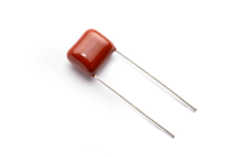
What Is a Coupling Capacitor?
A coupling capacitor is a capacitor used to block the DC component of the input signal. It works by allowing only the AC component of the signal to be passed through to the oscilloscope. The capacitor used may be:
- Ceramic
- An electrolytic capacitor
- A film capacitor
What Is a Coupling Switch?
A coupling switch is a switch that is used to select the type of coupling. Coupling switches are typically used to select between AC coupling and DC coupling. The switch may also be used to select between ground coupling and floating coupling.
The switch function works by allowing or blocking the passage of current. When the switch is in the AC position, it will enable only the AC component of the signal to pass through to the oscilloscope. When the switch is in the DC position, it allows all signal components to pass through.
Coupling Challenges and Solutions
| Coupling Challenages | Possible Solutions |
|---|---|
| It can add noise to the signal if you don't use the correct capacitor | Use a coupling capacitor to ensure unnecessary noise is blocked |
| Selecting the right coupling capacitor to prevent noise from being added to the signal | Ensure that it is the correct size for your signal, and the correct type of capacitor such as an electrolytic capacitor |
| Can be difficult to set up the coupling correctly | Refer to the applicable manual of your oscilloscope to help troubleshoot if you are having difficulty setting up the coupling. Or contact Keysight for technical support |
Coupling Advantages Summary
- Allows you to select which component of the signal you want to measure
- Helps to protect your oscilloscope from damage
- It allows you investigate how a circuit is operating without affecting its normal operation
- Can measure the strength of the signal, or the amplitude, without affecting the waveform
Browse Oscilloscopes at a Great Discount
Select up to 3 instruments to compare
Select another instrument to compare
![]()
Starting at
Select another instrument to compare
![]()
Starting at
Select another instrument to compare
![]()
Starting at
Keysight Oscilloscopes
When it comes to tech equipment, you want the best of the best. That's why Keysight oscilloscopes are the perfect choice for your needs. With industry-leading performance, they're the ideal tool for many applications. From basic signal analysis to complex measurements, Keysight digital oscilloscopes have you covered. With models ranging from entry-level to high-end, there's a Keysight oscilloscope that's perfect for your needs. So why settle for anything less? See Keysights Used Equipment to find a wide range of oscilloscopes to fit your needs.

Subscribe to Get Our Latest News, Updates, and Articles.
Popular Used Oscilloscopes
Keysight Used Oscilloscopes offers a wide range of industry leading pre-owened oscilloscopes, ranging from older generation Agilent oscilloscopes to the newest Keysight oscilloscope models. So whether you are a fist time buyer, replacing a model like-for-like or looking for upgrade – we have something for you.